
If you spot an error anywhere or disagree with anything mentioned on this page we will welcome your comments.
AIS - a practical explanation for those unfamiliar.
AIS (Automatic Identification System) can be thought of as a VHF radar system using 2 channels in the VHF marine band frequencies (161.975 MHz & 162.025 MHz). Designed as a collision avoidance system, it was made mandatory throughout the world in 2002 to be installed in all vessels of 300 gross tonnes and over and all passenger ships, More recently, within the European Union, this has been extended to include fishing vessels over a certain length which at the moment stands at vessels over 15 metres.
There are three classes of AIS; Class A, the type mandatory for commercial vessels, Class B for leisure and small craft and just available, Class B+, an enhanced version for leisure boats that sits around half way between Class A and Class B. All new Onwa AIS plotters are now equipped with Class B+ SOTDMA AIS modules. Class A is more sophisticated than Class B sending more detailed data out at a faster rate than Class B and will have transmit priority at all times. However, the introduction of Class B+ changes this as SOTDMA technology allows leisure users the same access to time slots as for Class A.
Class A is also much more powerful - transmitting at 12.5 watts whereas Class B is only 2 watts. B+, however, is a nice compromise for leisure sailors having a 5 watt transmission and the same faster SOTDMA technology of Class A.
For leisure sailors and small boat users AIS doesn't, and never will, replace true radar but it has certain advantages over radar. Better in one respect than conventional radar AIS can 'see' (to some extent) around corners as its wavelength is longer. Other advantages are considerably lower cost than radar and lower power consumption. Radar consumes a lot of power - at least X band does, whereas AIS current drain is quite small. My Onwa KP-1299A, with its large 12 inch screen consumes around 800 m/a whereas my radar is over 5 amps.
AIS - what does it look like?
You have probably seen AIS displayed as a radar ring or rings with your own vessel at the centre and nearby AIS transmitting vessels displayed as small triangles somewhere within the rings. This is an image of vessels that we can see from our AVES Marine base in Kent. The 'blob' of vessels just above the *red ring are transmissions coming from Tilbury Docks in London, about 8 miles away from us. Note that the outer ring in this example is set at 20nm so we are seeing vessels from as far away as 20nm.

*The red ring is a boundary set into the plotter by the user to trigger alarms, in this image the boundary is set at 6.5 miles, in practice this might me more or even less depending upon the traffic around your boat. In crowded waters, for example, you might set the ring a lot closer to reduce false alarms and in an open ocean situation very much further. We set out plotter alarm at 6.5 miles long distance in order to trigger an alarm from vessels in the River Thames and you can see this in our 2nd radar image below.
The red boxes on the right without any information in them are empty until a collision alarm is triggered, they then fill with details of the vessel calculated by the plotter to be on a collision course with your vessel.
Whilst the 'radar ring' is very useful to see what vessels are around your boat, it only gives you a representation of the vessels in your vicinity and has quite limited use. Look at the bright mass of light between the inner green and red rings, this is, in fact, several vessels but it isn't possible to know from this display anything about them - far better is to see them in real time overlaid on a chart. The benefit of seeing a large vessel displayed on your chart as a moving target in relation to your own boat has to be seen to realise just how valuable that is. At the moment my sailing yacht is moored on the River Midway in Kent. This is a river used by commercial and leisure vessels and it is reassuring to know from the AIS overlay on the chart on my Onwa plotter that whilst I am tacking across the river there isn't a huge freighter just around that blind band in the river.

Image showing three of the vessels shown in the the previous radar ring image but now overlaid on our chart and shows the vessels underway just outside Tilbury Docks. Note that the chart has been zoomed to a quite small area (as it would be for normal navigation) so only shows some of the vessels that can be seen on the radar ring.
This is so much clearer than the information we were previously presented with by just looking at the radar ring. Vessels will show a short line in front of them to indicate if they are underway and, as time passes they will leave a line behind them on the display showing their progress over the water. In the above image there are two vessels proceeding down the southern side of the river and a vessel is just leaving its mooring on the North bank and is beginning to also move down stream. You can see how much more informative this information is than just another target on the AIS Radar Ring. Were you navigating in this area the chart information with the three vessels shown would alert you instantly to their presence whereas the Radar Ring would be a meaningless jumble of targets.
Note...In real life your own vessel's position would also be shown at the centre of the chart enabling you to see where the 'big ships' are relative to your own position. However, as AVES Marine's base is inland from Tilbury, it would be confusing to show our own boat position some miles inland and also the zoomed out chart to show AVES Marine and Tilbury would reduce the detail to an impractical level .

Same image as previous but having placed the curser over the vessel leaving its mooring we can see its MMSI number, vessel name and position. More information on the vessel can be obtained from the AIS radar page/menu/AIS Detail List. Select the vessel name and press Enter.

Same vessel in the AIS ship list, we can see it is a Cypriot ship, that is 6.6 miles away on a course of 156 degrees. We don't have a name at this point but this would show were we to monitor the vessel for a slightly longer period. Whilst essential data is transmitted by Class A vessels every few seconds other information, such as name, is transmitted every six minutes so we have likely missed that part of the AIS transmission.
Advantages of an AIS Receiver
If you have ever had to cross a shipping lane in poor visibility you will know it can be a worrying event and suddenly seeing a merchant vessel emerging from the mist and bearing down upon you isn't something anyone will want to experience. However, with your AIS receiver you will have seen that vessel when it was several miles away and this, I think, really makes the case for AIS. Not only does the AIS show you AIS equipped vessels in your vicinity it also tell you quite a lot about them; their COG, SOG, name, MMSI number, type of vessel. Comforting is the knowledge that your Onwa AIS will alert you well before a real danger exists by the plotters collision alarm going off . If the vessel is approaching on a collision course and your avoiding action is uncertain this is the time to call the vessel by name on the VHS and alert the vessel to your position and course and your intentions. This is quite important as otherwise you might make a course change to avoid being run down at the same time as the commercial vessel does the same and you both stay on the collision course!
You may think from the previous comments that there is an implication that you need to spend the whole of your voyage with your eyes 'glued' to the plotter screen when, as a good skipper, you should actually be looking around you at all time. Of course, keeping a vigilant look out is what you must do and are required to do under maritime law. However, provided you have set up the collision warning alarms, which I will describe a little later in this article, you can leave it to the plotter to alert you to any vessel approaching that may enter the area around your boat that you consider (as defined by your own set-ups) is getting too close.
How far away can you 'see' other vessels?
How far away you can 'see' other vessels on an AIS receiver depends upon the height of the transmitting vessels antenna and the height of your own (VHF transmissions are line of sight). Large commercial vessels will have their own AIS aerial high up on their superstructure so line of site, even if your own aerial is mounted on a stern rail, will be quite good. Also, keep in mind that Class A vessels transmit at 12.5 watt whereas Class B and B+ transmit at only 2 and 5 watts respectively, so, whereas commercial vessels may be seen from many miles away, Class B will be seen only when fairly close up . For Class A reception it can be around 16 miles + and even more in unusual atmospheric conditions. On one occasion, whilst we were based in Gravesend, we received AIS transmissions from vessels in Denmark - around 500 miles! This was freak atmospheric conditions and only lasted around 2 hours. Class B leisure vessels will transmit at only 2 Watts power from an aerial likely much lower down so expect reception from other leisure boats to be considerably reduced over commercial vessels.
From our AVES Marine base in Kent we were able to see Class A vessels 23 miles away although it must be said that we are at quite a high point in Kent.
Transmitting distances
Transmission distances will be much lower than receive using Class B equipment and will be very dependent upon the aerial system components (AIS aerial, cable and connections) and height of the aerial, expect around 5 miles. Whilst this may seem a rather short distance, do keep in mind that a warning of a collision occurrence developing at 5 miles distance should be sufficient to avoid such a situation worsening. Some manufacturers of AIS equipment have adopted the new Class B+ AIS for leisure use (all current Onwa AIS transceivers are B+) which gives a small advantage in terms of transmission as a result of its greater 5 Watts power. Although a little over twice the power of Class B, this doesn't quite equate to twice the distance for transmission - even assuming a perfect aerial system. Class B+ expect 8 to 12 miles transmi. However, are other advantages that B+ has over ClassB. They use different technology, Class Bb using CSTDMA and Class B+ using SOTDMA. SOTDMA ia anm enhanced technology resulting in having no wait time for an AIS slot to transmit together with faster refresh rates. Also, transmission rates increase with speed, which is essential for fast moving power boats.
The table below shows the differences between the two systems.
Comparison SOTDMA and CSTDMA
| Comparison SOTDMA and CSTDMA | SOTDMA | CSTDMA |
| Transmit Power | 5 Watts | 2 Watts |
| Transmit refresh rate | 5 seconds | 30 seconds |
| Guaranteed Time Slot Allocation | Yes | No |
| Transmit Rate | 5 seconds | 30 seconds |
| Vessel at anchor/moored | 3 mins | 3 mins |
| SOG 0-2 knots | 3 mins | 3 mins |
| SOG 2-14 knots | 30 seconds | 30 seconds |
| SOG 2-14 knots and changing course | 30 seconds | 30 seconds |
| SOG 14-23 knots | 15 seconds | 30 seconds |
| SOG 14-23 knots and changing course | 15 seconds | 30 seconds |
| SOG > 23 knots | 5 seconds | 30 seconds |
| Other vessel information | 6 minutes | 6 minutes |
You can see that for a fast moving vessel, B+ is pretty much essential as waiting 30 seconds for your transmission to show a course change is just too long.
The additional information that the AIS receiver can bring to you:
Once you see a commercial vessel that is getting close to you it is a very easy process to find out the course and speed of the vessel. With Onwa plotters - by placing the curser over the target vessel its position and MMSI are displayed. Again, on Onwa plotters, an additional button press will bring up a window that shows; Name, MMSI number, Ship name, Call sign, position, SOG, COG, ship type and if it is underway. Note, however that although essential data such as position, COG,SOG and MMSI are refreshed at (for Class A) every 2 to 10 seconds when underway, other less essential data such as vessel name are transmitted less frequently so vessel name may not be immediately displayed.
Antenna considerations
AIS uses two channels at the upper end of the VHF marine band - 161.975 MHz & 162.025 MHz. A standard VHF antenna will receive AIS and also transmit it. However, a standard VHF antenna will not be ideal as it will be tuned around 156 MHz, the centre of the marine band, and not at the upper end where it should be for AIS. In practice, for a receiver, this isn't going to make a huge difference but for an AIS transmitter it is an entirely different matter. This is an important thing to consider as transmitting efficiency is much more dependent on your hardware than receiving only. Whilst any old VHF band antenna mounted anywhere may pick up transmissions from close up vessels, when it comes to transmitting a whole new set of problems arise - antenna design, height, impedance matching from transmitter output to antenna input, connector quality and probably the most often neglected factor - cable type. You may not be aware that a kink/tight bend in the cable, over tight cable ties - anything that compresses and distorts the dielectric insulator (the inner insulator around the centre conductor) may change the impedance and causes signal losses. Even without the added possibility of cable damage, signal loss over the cable is an inevitable significant factor; 50 ohm RG58 co-axial cable - very often used on small boats as it is cheap, thin and easy to install, has significant losses over long cable lengths; this cable is often packed with an AIS cable by manufacturers. RG58 usually works OK for reception, however, using RG58 for a transmitter is different as cable attenuation will definitely reduce your transmission efficiency - maybe to the point where it doesn't really work. If you are running more than 10 metres of cable for your new AIS install you should consider a lower loss cable although you will be looking at a thicker and more expensive cable. Possibly one of the best cables would be RG213 (the cable Radio Hams use) as it has very significantly lower signal loss over long distances, however, because of its thickness - around 10mm (RG58 is 5mm) it is unwieldy and very hard to install; its also a lot more expensive but the difficulty installing is more the reason for it not being ideal on a boat. A compromise would be RG8X which has lower loss than RG58 yet is considerably thinner than RG213 at 6.5 to 7 mm and cheaper also. In a nutshell, to receive AIS is possible on a standard marine VHF antenna mounted anywhere within reason on your boat but for AIS transmission you do need to consider the height of the antenna and also the possible losses in the connecting cable. However, as mentioned earlier you need to see and be seen by vessels close by not those many miles away. Seeing other vessels from 20 miles away is equally unnecessary although it does have a novelty value that a lot of sailors quite like.
 Cable comparison
Antenna height:
The higher your antenna the better will be your transmission and reception efficiency, particularly the former - it's that line of sight thing. However, as a collision avoidance system, you don't need to 'see' vessels 20 miles away, just the ones that are getting up close, so for receive AIS it isn't that important to get your antenna 30 feet up at the top of your mast. For transmission of AIS, however, we have that more stringent set of requirements that were mentioned earlier so higher the better is the rule together with the best cable possible. Always it has to be a compromise and do keep in mind that it is a close up warning system in the end.
Factors to mention regarding height; installing on top of a 30'+ mast will get you improved line of sight, but losses down a 30+ feet low grade, possible ancient, cable might negate that advantage. Some vessels, fishing and power boats, don't have tall masts so are obliged to mount antennas low down yet they can use AIS adequately, proving that height of the antenna is less important than most of us assume it to be. One further point regarding this, the vessels we are most concerned about are the 'big ships'. These vessels will have their AIS aerial mounted very high up on their superstructure which will greatly extend the line of site aspect.
Using your existing antenna:
It isn't possible to simply connect an AIS device to your existing VHF antenna because when your VHF is on transmit it will send up to 25 watts of R.F energy into the AIS receiver which will almost certainly not like the experience! With an AIS transceiver the problem goes both ways so you will possibly end up with frying both your VHF and the AIS.
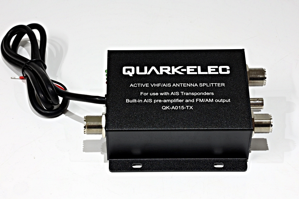
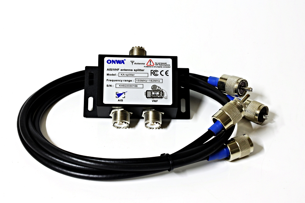
You can, however do this quite safely by installing an antenna switcher. Switchers come in two versions, passive and electronic. An electronic switcher is a device that prevents damaging either your VHF or the AIS device by allowing only one transmitter to transmit at any one time, preference will automatically be for the VHF. They are quite expensive to buy - for a transceiver antenna splitter it will likely set you back at least £200 - but will save the hassle of fitting a second antenna and running all that additional cable. Passive splitters connect together the two transmitters via components that will protect each one and these are a lot cheaper than an electronic version but there are losses that will effect both transmitters. Onwa manufacture such a device and that has a loss of 3 dB which is half the signal. Caution.....there are also boxes described as aerial splitters available on market-place sites that are simply a box that joins all the connectors together - absolutely avoid these completely as there is every chance that your equipment will be damaged. ly directly connecting an aerial to two devices result in massively high SWA and impedance changes that will render bothj aerials efgfectivy useless.
A recommended Quark-Elec transceiver electronic aerial switcher
Onwa passive aerial splitter - safe to use (Onwa warrants it) but 3dB signal loss on both transmitters
Using a dedicated second antenna for an AIS Receiver, where to mount it:
To avoid the hassle of mounting at the top of a mast or if you are a power boat user and have no other option I would go for one mounted on the push-pit or the roof of the cockpit. I say this from the practical experience of having a push-pit mounted dedicated AIS antenna which works fine for me as I see commercial shipping from 16 miles away. AIS devices may vary in their specification and the 16 miles that I can see with my KM12X may not be achievable with a less sensitive receiver. The present Onwa range of the AIS equipped models all have a highly sensitive AIS B+ unit which, apart from the increased transmission range using higher power Class B, have a receiver with a spec' that exceeds that of many other make receivers.
Onwa AIS transmit and receive specification:
Transmitter = greater than 5 Watt (37 dBm ± 1.5 dB
Receiver = less than -123dBm@20% PER
Why an AIS transceiver?
All the advantages of having an AIS receiver plus the knowledge that not only do you see the commercial vessels but that they see you also. For the relatively small difference in price between an AIS receiver and a transceiver (for Onwa products this is the case for other makes this may not be so) the transceiver version makes a lot of sense - just don't always assume that a commercial vessel sees you either, because the Bridge Watch may not be paying attention.
A frequently asked question that we receive: I want an AIS receiver but am unsure if I want to transmit my position via AIS what would you advise?
Answer: Go for the transceiver, you can operate the device with the transmit turned off so in essence you have just a receiver, however, if at some point you want to transmit your vessel's position you have the option of doing so by turning the transmitter on - I can pretty much guarantee that you will do this as soon as that mist starts to come down! The difference in price is small (for Onwa plotters) so you have the best of both worlds.
Using a dedicated second antenna for an AIS Transceiver:
As I previously mentioned when discussing AIS antenna for reception, AIS is intended as a warning system for close up possible collision situations. That, together with the low transmitting power of Class B and even B+, means that although you may see commercials from 16 or more miles away they won't see you until both vessels are very much closer. This isn't a negative aspect of Class B as I doubt whoever is in charge of that commercial vessel 16 miles away is particularly interested in another vessel at that sort of distance. However, at 5 or less miles they probably will be - so think close up when you are thinking about AIS transmitting distance.
My feeling is that if you go for an AIS transceiver you need everything going for you so a B+ transceiver is almost a must (all Onwa AIS devices are Class B+) and an antenna as high as possible connected to the AIS device via the best low loss cable. This may be a case for an antenna switcher but, bearing in mind that a standard VHS antenna is not ideally tuned for AIS, this might actually suggest the need for a second antenna at the top of the mast although the hassle of installing it is another matter! Also there is a problem of interaction fitting two similar aerials close together, mounting at different heights is the best way to do this. Of course, if your vessel is a power vessel without a 30' mast then this is all academic as you are obliged to transmit from low level. In this case get the best aerial you can, an Onwa B+ transmitter, and connect it with a low loss cable.
Further notes on an Onwa AIS enabled plotter settings that may be useful:
Using an Onwa AIS plotter
Collision Alarm Settings
In the AIS menu on Onwa plotters there are three user settings that you need to set up for the plotter to calculate collision alerts and alarms. usage and experience will make clear what the appropriate setting might be for your particular circumstance and environment.
Activation ring:
Set this as a kind of barrier around your boat where any Class A or B equipped vessel entering the ring will be tracked by the plotter and will trigger an alarm should the plotter compute that a collision may at some point occur (set by your CPA and TCPA settings)
CPA - Closest Point of Approach
CPA is set to the distance that the user feels is as close as he wants another vessel to get before being warned that the possibility of a collision may exist. The plotter computes from the other vessels position, COG and SOG and warns if a vessel is calculated to come within the distance that has been set in the CPA Limit box in the AIS Menu.
TCPA - Time to Closest Point of Approach
TCPA is set by the user to the time that he wants to be warned that another vessel is computed by the plotter to get to the point where it enters the CPA limit that has been set.
As an example:
You need to decide how close you want to let other vessels get to you (CPA) before an alarm sounds and also how much time (TCPA) it will be before before the vessel gets to that point. For instance, you might decide that 0.5 nm is plenty much close enough for large vessels to pass by you and you want to have 10 minutes notice so that you have time to take avoiding action and, if you are unsure what the other vessel may do, call them on the radio using the information that comes up on your plotter in the red boxes on the AIS radar ring page (True for Onwa plotters; others may be different in the way that they display warnings).
On an Onwa plotter. a vessel that may represent a real and present danger will show on the AIS radar screen as red and flashing.
An alarm has been triggered

A vessel has entered the area that we have defined as being close enough before we want to know about it. The alarm message, which appears in the usually empty red boxes, tells us that the vessel, KEW, will be at that point in 6.2 minutes when it will then be at our set limit of 6.4 nm away
Note that the ring setting has been made unrealistically far away in this example as our AVES Marine land based site is quite a way from any actual vessels. In practice this distance would be much shorter.
A word of advice: when in crowded waters it may be best to turn alarms off to avoid constant alarms. However, using your Onwa plotter's chart you can still visually track nearby AIS equipped vessels and, as always keep a good look out at all times.
You Tube video of interest
Demonstration of a (now) obsolete model KP8299A, 8" plotter with AIS transceiver in Hong Kong Harbour. Here Vincent Wong Chairman of Onwa sets up the 8299A on one boat which will travel around the harbour while Vincent tracks it from another that is stationary. It is useful as it demonstrates how the plotter on the stationary boat that Vincent is on can track the 8299A on his other boat by way of speed and course. Note how the vessel with the 8299A is represented on the chart of the receiving boat by a triangle with a short line to the front indicating the heading of the boat and a longer line to the rear showing its passage over the ground.
Note: the patterns in the video that appear on the screen from time to time are not visible in real time to the plotter user - they are a phenomena produced by the video camera and are known as moiré effect. The plotter being used for this demo is not a UK version and the fascia controls and other aspects are written in Chinese. Plotters produced for UK use are all in English. By the way, Onwa plotters are multilingual as far as the menu options are concerned. Language is selected in the menu and all text used by the plotter will be in your language of choice.
Live link to map of AIS equipped vessels in the English Channel, click on the link. http://www.fullthrottleboatcharters.com/ship-tracker/
For Technophobes and mathematicians this is the way that Onwa chart plotters calculate the collision warnings CPA and TCPA:
CPA = closest point of approach for 2 boats P and Q, distance between P and Q at closest point of approach.
TCPA = time to closest point of approach
t = time
t0 = start time, now, the time of current calculation
P(t) = position longitude + latitude at time t, let's say P is our boat P (position, velocity u COG+SOG by Onwa-GPS)
Q(t) = position longitude + latitude at time t of other boat Q, position, velocity v transmitted to us/Onwa-GPS by AIS data !
u = velocity/speed vector of boat P in course COG + speed SOG, given by Onwa-GPS
v = velocity/speed vector of boat Q in course + speed, given by AIS
u and v have always the values of t0 , now, the time of current calculation !
P(t0) and Q(t0) are the positions at start time, now, the time of calculation.
|w(t)| = d(t) = distance between boats P + Q at time t, in nautical miles.
w0 = |P(t0) - Q(t0)| = distance between boats P + Q at time t0, current time of calculation, now.
Positions of boats P + Q at any future time t, calculated by vectors u + v and positions now, at start t0, time of current calculation:
P(t) = P(t0) + t * u , u and v as vectors, each pairs of values of COG + SOG for boats P + Q.
Q(t) = Q(t0) + t * v , u and v as vectors, each pairs of values of COG + SOG for boats P + Q.
d(t) = |P(t) - Q(t)| = |w(t)| , distance between boats P + Q at any time t
w(t) = w0 + t * (u - v) , u and v as vectors, each pairs of values of COG + SOG for boats P + Q.
So far we have defined now all values and basic equations.
We get now directly (according to reference) the time of closest point of approach = tcpa :
tcpa = -w0 * (u - v) / |u - v|^2
If |u - v| = 0 then tcpa = 0 by practical definition.
If tcpa < 0 then cpa closest point of approach was already in past, distances between boats P + Q are increasing, no problems.
After Onwa-plotter calculated tcpa , it can calculate cpa = distance between boats P + Q at time tcpa, d(tcpa).
Distance cpa at time tcpa:
(time tcpa = time(now) + tcpa)
cpa = d(tcpa) = P(tcpa) - Q(tcpa) in nautical miles